Arduino Mega 2560能够读取0 ~ 5V的电压,并转换为10bit即0~1023级的数字信号。这怎么理解呢?
分类: Arduino
Arduino 是一款便捷灵活、方便上手的开源电子原型平台,包含硬件(各种型号的arduino板)和软件(arduino IDE)。它适用于艺术家、设计师、爱好者和对于“互动”有兴趣的朋友们
Ubuntu 16.04软件中心安装的Arduino IDE报告错误 – avrdude: ser_open(): can't open device "/dev/ttyACM0": Permission denied
最近要使用Arduino开发一个读取电压的装置,新电脑上没有安装Arduino IDE,因此,从Ubuntu 16.04软件中心中搜索找到一个名为arduino-mhall119的软件,如下图所示:
继续阅读Ubuntu 16.04软件中心安装的Arduino IDE报告错误 – avrdude: ser_open(): can't open device "/dev/ttyACM0": Permission denied
How to successfully build packages for WD My Cloud from source
The WD My Cloud comes with a Debian wheezy system on it. However WD customized that in a way that it is hardly possible (if not impossible at all) to install new packages using the standard "apt-get install <package name>" way, especially when you update the device firmware to version 4.x or later. The latest firmware, in fact, uses a modified Debian system with 64K sized memory pages: if you install a package using "apt-get install <package name>" from the standard repositories, almost certainly it won't run and produce just a laconic "Killed" output.
继续阅读How to successfully build packages for WD My Cloud from source
继续阅读How to successfully build packages for WD My Cloud from source
Install the Arduino IDE in Ubuntu 12.04
转自http://blog.markloiseau.com/2012/05/install-arduino-ubuntu/
Install the Arduino IDE in Ubuntu 12.04
Installing the Arduino IDE in Ubuntu only takes a few minutes. As usual, it’s a better idea to install the Arduino straight from the source, instead of relying on the version in Ubuntu’s repository. While it wasn’t hard to install the Arduino IDE, I noticed that the Arduino GUI was really slow and laggy. This is because the startup script tells Java to use Ubuntu’s GTK look and feel, which makes everything run slowly. It’s easily fixed by changing a single line in the startup script.
Update: In the Arduino 1.0.1 update, “Serial Port” is greyed out. The fix is outlined in the troubleshooting section.
Install the Arduino IDE in Ubuntu
- Install gcc-avr, avr-libc and openjdk-6-jre if you don’t have it already.
- Plug in the board, see where it’s connected
- Download and unpack the Arduino IDEtarball
- Run the IDE
- Select your board model and serial port
- Run a sample program
- Fix the buggy interface (optional)
- Troubleshooting
Everything worked out of the box, other than the interface.
Install gcc-avr and avr-libc
Gcc-avr and avr-libc give your system the tools it needs to compile c into AVR machine code:
|
1 |
$ sudo apt-get install gcc-avr avr-libc |
If you don’t have openjdk-6-jre already, install and configure that too:
|
1 2 3 |
$ sudo apt-get install openjdk-6-jre $ sudo update-alternatives --config java (select the correct JRE if you have more than one installed) |
Once those are installed plug in your board and type $ dmesg . It will print the kernel’s ring buffer and show you what USB port your Arduino is plugged into:
|
1 2 3 4 5 6 |
$ dmesg -- snip -- [226470.727790] usb 1-1.1: new full-speed USB device number 6 using ehci_hcd [226470.861077] cdc_acm 1-1.1:1.0: ttyACM0: USB ACM device [226470.861654] usbcore: registered new interface driver cdc_acm [226470.861659] cdc_acm: USB Abstract Control Model driver for USB modems and ISDN adapters |
According to dmesg, our board is plugged into ttyACM0.
Download and Run the Arduino IDE
Go to the downloads page on Arduino’s download page to get the latest Arduino IDE tarball (.tgz file) for your architecture. My laptop is 64-bit, so I chose accordingly. Once the file was finished downloading, I unzipped and ran it with the following command:
|
1 2 3 4 |
~/Downloads$ tar xzvf arduino-1.0.1-linux64.tgz ~/Downloads$ cd arduino-1.0.1 ~/Downloads/arduino-1.0.1$ ./arduino ./arduino launches the Arduino IDE. |
Select your board model and serial port
I’m using an Arduino MEGA 2560, so I went to Tools>Board>”Arduino Mega 2560 or Mega ADK.” At this point, I noticed that the GUI was really slow and hard to use. If you want to fix it before proceeding, exit the IDE and skip to the ”Fixing the Interface” section before proceeding.
The IDE flashed an error about how my board wasn’t accessible over the COM1 port. COM1 usually refers to a 9-pin serial port, and my laptop doesn’t even have one. I went to Tools>Serial Port and selected /dev/ttyACM0, which reflected the output I saw when I checked dmesg.
The errors went away, and I went to File>Examples>Basics>Blink and clicked upload. Sure enough, the LED started blinking. You should be ready to start writing and running Arduino programs!
Fix the Arduino IDE to make it run more smoothly in Ubuntu
Exit the Arduino IDE and go to the installation folder (the folder you unzipped from the .tgz file). Edit the “arduino” script in your favorite text editor. To make Arduino use the native Swing windowing instead of forcing the GTK look and feel, which is the cause of the bugginess, change the following line:
|
1 2 3 4 |
#comment out this line: #java -Dswing.defaultlaf=com.sun.java.swing.plaf.gtk.GTKLookAndFeel processing.app.Base #change it to this: java processing.app.Base |
Just delete the -D flag and its argument. Personally, I get nostalgic about the old-school Swing look and feel, but either way, it fixed all of the lagginess issues I was experiencing.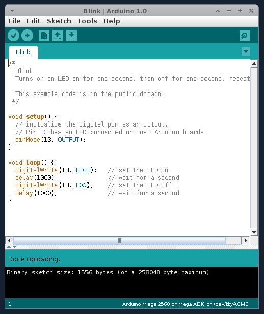
My Arduino IDE, running in Ubuntu (using SWT instead of GTK)
Troubleshooting USB and the grayed out Serial Port
When I got the Arduino 1.0.1 update, “Serial Port” was grayed out in the tools menu. Running arduino as root ( sudo ./arduino) resolved the issue, but it’s not an acceptable solution. In my case, serial port was grayed out because my user didn’t have permission to read and write to the device.
I added my user to the dialout group with the command sudo usermod -a -G dialout mark . Usually, that would have fixed it but iserial port was still grayed out.
Changing the permissions on /dev/ttyACM0 to world readable and writeable fixed the grayed out serial port. I ran sudo chmod a+rw /dev/ttyACM0 and the serial port menu worked again.
I’ve noticed that running programs that send lots of data over USB can cause issues with the arduino programming software, making it give errors while uploading code. Holding down the reset button fixed my upload and USB errors in most cases.
Further Reading
If you read nothing else before you start writing programs, look at the official Arduino Reference page. It might be the most concise, complete language reference I’ve ever seen.
Arduino小车更换锂电池导致过载的问题分析
一直是用四节镍氢电池来作为小车的电源,某天在网上看到了一个 5V,9V,12V的多用锂电池电源,忍不住就买了个过来,本以为很轻松的换上就可以了,结果当接到12V的电源口子上面的时候,总是自动断开,进入保护模式,感觉很奇怪。
电源图片

该电源提供1.5A的极限电流,过流以后会自动切断电源。
感觉尽管小车有四个马达,但是功率不至于达到 12V*1.5A 这么恐怖的地步。
最后用我的直流电源来分析,得到惊人的发现平时的电流也就在300mA左右,但是,某个瞬间,会直接飙升到2.24A以上,这个电流实在是有些恐怖。
直流电源如下:

百思不地其解,究竟是为什么导致如此大的瞬间过载电流,幸好电源有过流保护,否则,非出事不可,锂电池可是标准的易燃易爆啊。
细想之下,发觉问题出在如下的代码上面
|
1 2 3 4 5 6 7 8 9 10 11 12 13 14 15 16 17 18 19 20 21 |
digitalWrite(MosfetLeftFrontWheel0, HIGH); digitalWrite(MosfetRightFrontWheel0, HIGH); digitalWrite(MosfetLeftTailWheel0, HIGH); digitalWrite(MosfetRightTailWheel0, HIGH); digitalWrite(MosfetLeftFrontWheel1, LOW); digitalWrite(MosfetRightFrontWheel1, LOW); digitalWrite(MosfetLeftTailWheel1, LOW); digitalWrite(MosfetRightTailWheel1, LOW); delay(200); //停车 digitalWrite(MosfetLeftFrontWheel0, LOW); digitalWrite(MosfetRightFrontWheel0, LOW); digitalWrite(MosfetLeftTailWheel0, LOW); digitalWrite(MosfetRightTailWheel0, LOW); digitalWrite(MosfetLeftFrontWheel1, LOW); digitalWrite(MosfetRightFrontWheel1, LOW); digitalWrite(MosfetLeftTailWheel1, LOW); digitalWrite(MosfetRightTailWheel1, LOW); |
这段代码看似没有问题,当时也是为了方便才这样写的。
请注意 “停车”这两个字,当时为了使得小车在获得超声传感器的反馈后才会动作,因此要求小车运动一段距离以后就要停下来等待传感器。
但是如此操作导致一个严重的问题,那就是电机的启动负载问题,电机的启动电流非常大,频繁启动,尤其是多电机同步,会导致不可预测的瞬时启动功率过载,非常危险。小车可是有四个驱动电机啊!
虽然知道原因了,但是,却不好解决,原因在于,直流电机的软启动,国内的技术,唉,不提也罢,随便一个配件都是进口的,都要几张红的,关键是还没有给小车这么小的电机的专用的驱动模块,太难了,也不合适。
没办法,不过可以通过降低启动电压的方式来降低瞬时功率,代价就是电机输出功率的下降。于是把电压切换到9V,瞬时最大峰值电流一下子降到了1.2A左右。
勉强凑合。
不过最根本的解决方法,恐怕还是PWM来降低速度,电机一旦启动,就不要停下来,反而是最节能,最不容易烧毁控制芯片的。
的确是个问题。
Arduino PWM控制逻辑
对于直流电机的速度控制,目前流行的控制逻辑是PWM,关于 Arduino 的PWM,看看图片

板子上标注了“PWM”的区域就是管脚均可以用于这种输出。使用的函数是:
|
1 |
analogWrite(pin, value); |
注意value值的范围是0~255。
PWM 英文是“Pulse-width modulation” ,PWM是用占空比不同的方波,来模拟“模拟输出”的一种方式。简而言之就是电脑只会输出0和1,那么想输出0.5怎么办呢?于是输出01010101….,平均之后的效果就是0.5了。
现在看看电机的常规驱动电路,H桥

使用单片机来控制直流电机的变速,一般采用调节电枢电压的方式,通过单片机控制PWM1,PWM2,产生可变的脉冲,这样电机上的电压也为宽度可变的脉冲电压。根据公式
U=aVCC
其中:U为电枢电压;a为脉冲的占空比(0<a<1);VCC直流电压源,这里为5V。
电动机的电枢电压受单片机输出脉冲控制,实现了利用脉冲宽度调制技术(PWM)进行直流电机的变速。

因为在H桥电路中,只有PWM1与PWM2电平互为相反时电机才能驱动,也就是PWM1与PWM2同为高电平或同为低电平时,都不能工作,所以上图中的实际脉冲宽度为B,
我 们把PWM波的周期定为1ms,占空比分100级可调(每级级差为10%),这样定时器T0每0.01ms产生一次定时中断,每100次后进入下一个 PWM波的周期。上图中,占空比是60%,即输出脉冲的为0.6ms,断开脉冲为0.4ms,这样电枢电压为5*60%=3V。
我们讨论的是可以正转反转的,如果只按一个方向转,我们就只要把PWM1置为高电平或低电平,只改变另一个PWM2电平的脉冲变化即可,,如下图(Q4导通,Q3闭合,电机只能顺时针调整转动速度)

下面看看摘抄的部分原理
直流电动机转速n=(U-IR)/Kφ
其中U为电枢端电压,I为电枢电流,R为电枢电路总电阻,φ为每极磁通量,K为电动机结构参数。
直 流电机转速控制可分为励磁控制法与电枢电压控制法。励磁控制法是控制磁通,其控制功率小,低速时受到磁饱和限制,高速时受到换向火花和换向器结构强度的限 制,而且由于励磁线圈电感较大动态响应较差,所以这种控制方法用得很少。大多数应用场合都使用电枢电压控制法。随着电力电子技术的进步,改变电枢电压可通 过多种途径实现,其中PWM(脉宽调制)便是常用的改变电枢电压的一种调速方法。
PWM调速控制的基本原理是按一个固定频率来接通和断开电源,并根据需要改变一个周期内接通和断开的时间比(占空比)来改变直流电机电枢上电压的"占空比",从而改变平均电压,控制电机的转速。在脉宽调速系统中,当电机通电时其速度增加,电机断电时其速度减低。只要按照一定的规律改变通、断电的时间,即可控制电机转速。而且采用PWM技术构成的无级调速系统.启停时对直流系统无冲击,并且具有启动功耗小、运行稳定的特点。
设电机始终接通电源时,电机转速最大为Vmax,且设占空比为D=t/T,则电机的平均速度Vd为:
Vd=VmaxD
由公式可知,当改变占空比D=t/T时,就可以得到不同的电机平均速度Vd,从而达到调速的目的。严格地讲,平均速度与占空比D并不是严格的线性关系,在一般的应用中,可将其近似地看成线性关系。 在直流电机驱动控制电路中,PWM信号由外部控制电路提供,并经高速光电隔离电路、电机驱动逻辑与放大电路后,驱动H桥下臂MOSFET的开关来改变直流电机电枢上平均电压,从而控制电机的转速,实现直流电机PWM调速。
原理知道了,那么看看 Arduino Mega 2560 的PWM控制端口信息
1) Arduino 2560 has 12 pins supporting PWM. They are from 2 to 13 included.
2) the PWM default frequency is 490 Hz for all pins, with the exception of pin 13 and 4,whose frequency is 980 Hz (I checked with an oscilloscope).
3) In order to change frequency on pin 'A', we have to change some value in the timer (or register), controlling pin 'A'. This is the list of timers in Arduino Mega 2560:
timer 0 (controls pin 13, 4);
timer 1 (controls pin 12, 11);
timer 2 (controls pin 10, 9);
timer 3 (controls pin 5, 3, 2);
timer 4 (controls pin 8, 7, 6);
As you can see, a given timer controls more than one pin (every change about a timer will affect all pins depending on it!).
4) You can access a timer simply changing in your code (tipically in the setup()), the value of variable TCCRnB, where 'n' is the number of register. So, if we want to change the PWM frequency of pins 10 and 9, we will have to act on TCCR2B .
5) The TCCRnB is a 8 bit number. The first three bits (from right to left!) are called CS02, CS01, CS00, and they are the bits we have to change.
Those bits in fact represent an integer number (from 0 to 7) called 'prescaler' , that Arduino uses to generate the frequency for PWM.
6) First of all, we have to clear these three bits, i.e they must be all set to 0:
|
1 2 |
int myEraser = 7; // this is 111 in binary and is used as an eraser TCCR2B &= ~myEraser; // this operation (AND plus NOT), set the three bits in TCCR2B to 0 |
7) now that CS02, CS01, CS00 are clear, we write on them a new value:
|
1 2 |
int myPrescaler = 3; // this could be a number in [1 , 6]. In this case, 3 corresponds in binary to 011. TCCR2B |= myPrescaler; //this operation (OR), replaces the last three bits in TCCR2B with our new value 011 |
now we have a new PWM frequency on pin 9 and 10!
I registered those values on all PWM pins, changing the value of prescaler (the only exception are pins 13 and 14, see later):
prescaler = 1 ---> PWM frequency is 31000 Hz
prescaler = 2 ---> PWM frequency is 4000 Hz
prescaler = 3 ---> PWM frequency is 490 Hz (default value)
prescaler = 4 ---> PWM frequency is 120 Hz
prescaler = 5 ---> PWM frequency is 30 Hz
prescaler = 6 ---> PWM frequency is <20 Hz
(prescalers equal t 0 or 7 are useless).
Those prescaler values are good for all timers (TCCR1B, TCCR2B, TCCR3B, TCCR4B) except for timer 0 (TCCR0B). In this case the values are:
prescaler = 1 ---> PWM frequency is 62000 Hz
prescaler = 2 ---> PWM frequency is 7800 Hz
prescaler = 3 ---> PWM frequency is 980 Hz (default value)
prescaler = 4 ---> PWM frequency is 250 Hz
prescaler = 5 ---> PWM frequency is 60 Hz
prescaler = 6 ---> PWM frequency is <20 Hz
Note that timer 0 is the one on which rely all time functions in Arduino: i.e., if you change this timer, function like delay() or millis() will continue to work but at a different timescale (quicker or slower!!!)
明天修改一下电机的控制代码,把小车代码修改一下,哈哈
编写Arduino支持的C++类库
以下为摘抄的例子,已经亲自验证过,例子是正确的
我们在上一讲中实现了一个TN901红外温度传感器51程序到Arduino程序的转换,如果代码越来越多这样程序的可维护性会随之降低,也不适合团度开发。我们应该把常用的文件封装成C++库,这样在复用的时候就会方便很多。
首先让我们来看下官方的C++类库是怎样的结构,以官方的LCD类库为例,如下图所示:

上面的文件大体是这样的结构:
| 文件名 | 文件类型 | 文件说明 |
| keywords.txt | keywords.txt | Arduino库色标文件 |
| LiquidCrystal.h | .h | C++头文件 |
| LiquidCrystal.cpp | .cpp | C++程序文件 |
以下几种文件的作用如下:
.h 头文件:头文件作为一种包含功能函数、数据接口声明的载体文件,用于保存程序的声明(declaration),而定义文件用于保存程序的实现 (implementation)。
.cpp 文件:C++程序源文件主要的逻辑写在这里。
keywords.txt 文件:用来定义库在程序中显示关键字的颜色。
首先我们来尝试下头文件的编写
|
1 2 3 4 5 6 7 8 9 10 11 12 13 14 15 16 17 18 19 20 21 22 23 24 25 26 27 28 29 |
#ifndef TH901_H //根据条件进行编译 #define TH901_H //我们在这中间添加程序主体的代码部分,首先来添加程序的头文件,需要引用什么都可以加进来 #include <inttypes.h> //引用相关的头文件 //之后我们可以预定义一些需要的常量,这样维护起来比较方便,如果常量值改变只要统一修改这里就好 #define TN901_OTADDRESS 0x4c #define TN901_ETADDRESS 0x66 #define TN901_ENDADDRESS 0x0d //接下来我们来定义变量和声明程序的方法,需要外部调用和访问的就声明成public,不需要外部访问的就声明为private class TN901 //定义类主体及类名 { public: //以下定义为公共方法 short ET; //环境温度输出 short OT; //目标温度输出 void Init(int TN_Data,int TN_Clk,int TN_ACK); //程序初始化 void Read(); //读取方法 void ReadData(char flag); //读取指定地址的数据 int GetData(); //获取数据 private: //以下定义为私有方法 int _dataPin; //数据引脚 int _clkPin; //时钟引脚 int _ackPin; //反馈引脚 unsigned char Data[5]; //数据数组 }; #endif//程序结束 |
这样我们一个头文件就写好了.
接下来我们来书写程序的主体,就是CPP文件。
|
1 2 3 4 5 6 7 8 |
//首先我们引用已经写好的程序头文件 #include "TN901.h" //之后我们引用一些需要的库文件 #include "TN901.h" #include <stdio.h> #include <string.h> #include <inttypes.h> #include "Arduino.h" |
然后我们逐一实现在头文件中定义的方法,注意类型要与定义类型相对应。所有的方法都要属于你定义的类名,格式如下
类名::方法名
另外i啊我们要为程序的封装考虑程序应有的结构,总之是怎样使你的库使用起来最方便,在一般的逻辑中尽量减少调用的次数。我们可以把程序的逻辑分割为几个部分来书写。如:
1.初 始 化
2.实现功能
3.显示数据
当然这个逻辑以具体的程序为准。
我们来尝试写第一个初始化的方法,这样我们可以自己定义程序的端口。
|
1 2 3 4 5 6 7 8 9 10 11 12 |
//初始化TN901传感器 void TN901::Init(int TN_Data,int TN_Clk,int TN_ACK) { //定义私有端口 _dataPin=TN_Data; _clkPin=TN_Clk; _ackPin=TN_ACK; pinMode(_clkPin, INPUT); pinMode(_ackPin, OUTPUT); digitalWrite(_ackPin,HIGH); } |
然后我们书写程序的主要逻辑部分
|
1 2 3 4 5 6 7 8 9 10 11 12 13 14 15 16 17 18 19 20 21 22 |
//读取数据 void TN901::Read() { digitalWrite(_ackPin,LOW); ReadData(TN901_OTADDRESS);//目标温度的第一个字节为0x4c if((Data[0]==TN901_OTADDRESS)&& (Data[4]==TN901_ENDADDRESS))//每帧的最后一个字节为0x0d { GetData_OT(); } delay(1); //等待1毫秒 digitalWrite(_ackPin,LOW); ReadData(TN901_ETADDRESS);//环境温度的第一个字节为0x66 if((Data[0]==TN901_ETADDRESS)&& (Data[4]==TN901_ENDADDRESS))//每帧的最后一个字节为0x0d { GetData_ET(); } } |
最后我们逐一实现程序的运算过程
|
1 2 3 4 5 6 7 8 9 10 11 12 13 14 15 16 17 18 19 20 21 22 23 24 25 26 27 28 29 30 31 32 33 34 35 36 37 38 39 40 41 42 43 44 45 46 |
//读取数据 void TN901::ReadData(char flag) { char i,j,k; byte BitState = 0; //每次发七帧 for(k=0;k<7;k++) { for(j=0;j<5;j++) //每帧5个字节 { for(i=0;i<8;i++) { int temp= digitalRead(_clkPin); while(temp) { temp = digitalRead(_clkPin); } temp= digitalRead(_clkPin); BitState= digitalRead(_dataPin); Data[j]= Data[j]<<1; Data[j]= Data[j]|BitState; while(!temp) { temp = digitalRead(_clkPin); } } } if(Data[0]==flag) k=8; } digitalWrite(_ackPin,HIGH); } //计算环境温度 void TN901::GetData_ET() { ET=(Data[1]<<8)|Data[2]; ET = int(((float)ET/16 - 273.15)*100); } //计算目标温度 void TN901::GetData_OT() { OT=(Data[1]<<8)|Data[2]; OT = int(((float)OT/16 - 273.15)*100); } |
之后我们来尝试为我们的库编写一个范例程序来测试我们的程序是否运行正常。
|
1 2 3 4 5 6 7 8 9 10 11 12 13 14 15 16 17 18 19 20 21 22 23 24 |
#include <TN901.h> //引用库文件 TN901 tn; //实 例 化 void setup() { Serial.begin(9600); tn.Init(7,9,8); //初 始 化 } void loop() { tn.Read(); //数据读取 SerialValue(); delay(200); } void SerialValue() { Serial.print("OT: "); Serial.print(tn.OT, DEC); //输出目标温度 Serial.println(" C"); Serial.print("ET: "); Serial.print(tn.ET, DEC); //输出环境温度 Serial.println(" C"); } |
好了,我们看到虽然我们花了一点时间编写了库文件,但是在我们使用程序的时候可以非常方便的调用,而且这样逻辑会比较清晰。呵呵。
最后送给大家一个小礼物,就是如何为我们的库编写色标文件,色标文件就是定义你的库中的方法在编译器中显示的颜色
没有色标文件的库显示起来是这样的:

我们可以看到库文件的类名和方法名都是黑色的这样看起来不是很清楚。加上色标文件之后是这样的

我们可以看到TN901这样的类名都被加亮了这样看起来要清楚许多。
实现这个需要定义一个色标文件放在库文件的目录中,格式如下
|
1 2 3 4 5 6 7 8 9 10 11 12 13 14 15 16 17 18 19 20 21 22 23 24 25 |
####################################### # Syntax Coloring Map For 你的类名 ####################################### ####################################### # Datatypes (KEYWORD1) 数据类型关键字 ####################################### TN901 KEYWORD1 ####################################### # Methods and Functions (KEYWORD2) 方法类型关键字 ####################################### Init KEYWORD2 Read KEYWORD2 ReadData KEYWORD2 GetData KEYWORD2 ####################################### # Constants (LITERAL1) 常量类型关键字 ####################################### ET LITERAL1 OT LITERAL1 |
这样我们的色标文件就写好了,我们把它保存成文件名为keywords.txt的文件放在库文件目录下就可以了。
当我们些库文件全部做好了之后我们就可以把这些文件放在,这样的目录下
energia:energia-0101E0008\hardware\msp430\libraries\
arduino:arduino-1.0.1-windows\arduino-1.0.1\libraries\
这样当你重新打开官方编译器的时候可以看到如下的内容

Arduino小车的制作
最近在琢磨Arduino,淘宝了很多,决定做个小车来玩玩,很简单,结果却折腾了许久。算是刚刚上道。废话少说,先上一张初步成品图片。

来一张没有盖上盖子的,盒子内部是一个四路直流电机驱动模块。
 具体的直流电机驱动模块的图片如下
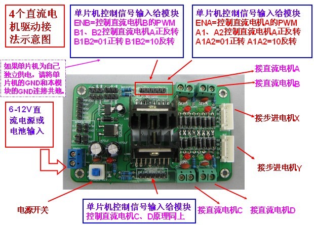
具体的接线部位的照片
 注意接线点,途中的D1,D2 为一个电机的控制信号线,C1,C2 为另一个电机的控制线,传输的信号可以为 00,01,10,11四种信号,控制电机的正反转动。
图中的黄线和蓝线,是连接电机的线。
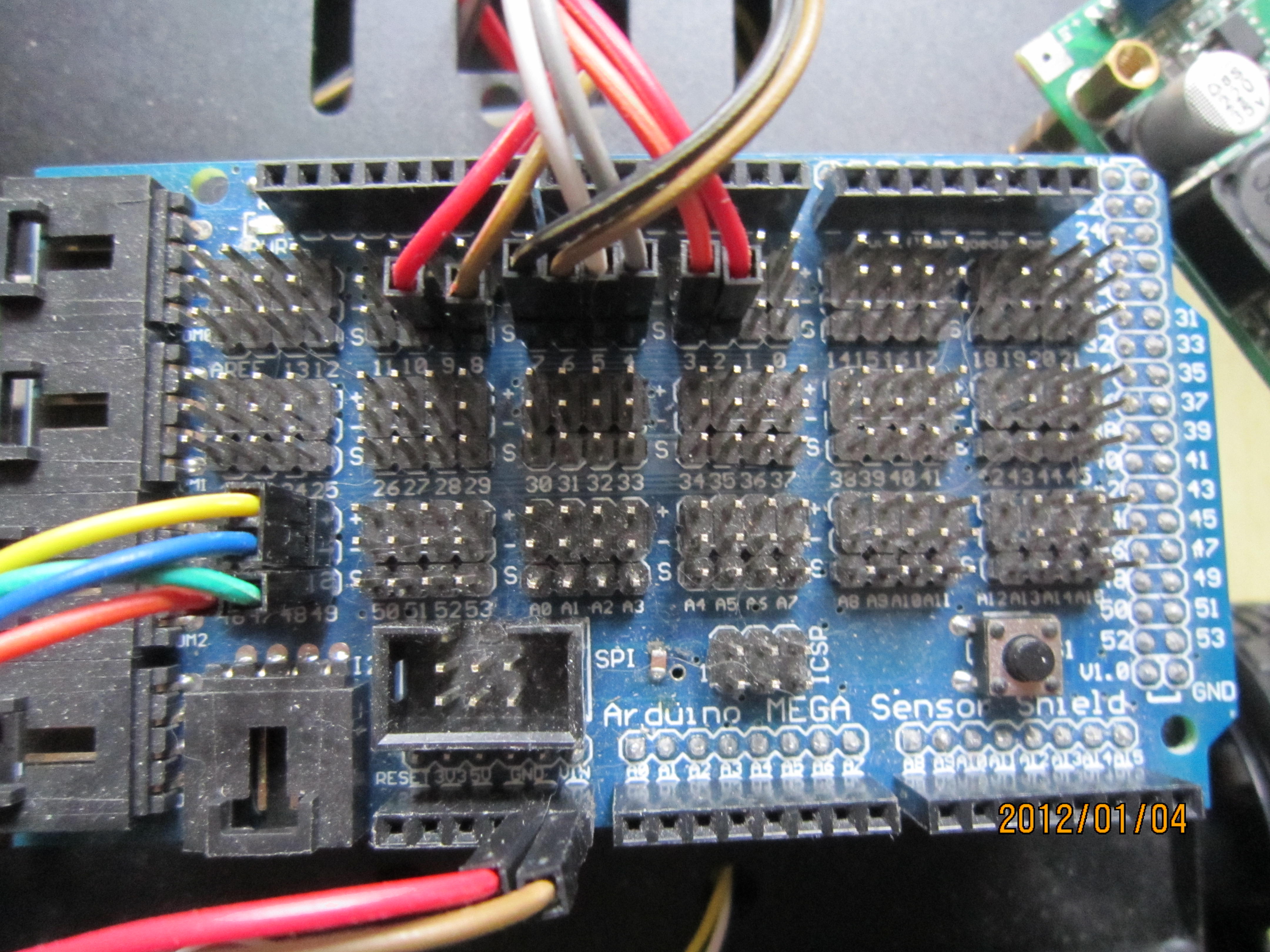
控制板为 Arduino MEGA2560 的主板外加传感器扩展版。

扩展版的图片为

组合在一块以后,电机控制板与Arduino 2560 的控制板的具体接线为

注意的情况是,这个扩展版的正负极印反了,因此凡是标记着 “+”的为负极,凡是标记着“-”的为正极。
具体的情况根据实际情况来,如D1,D2 与 7,8 号线连接,通过控制这两个端口的信号的高低来控制控制电机控制板。
注意控制板上面的标记着VIN和GND的那个插点,那个是外界电源的插点。
具体的插点,看图
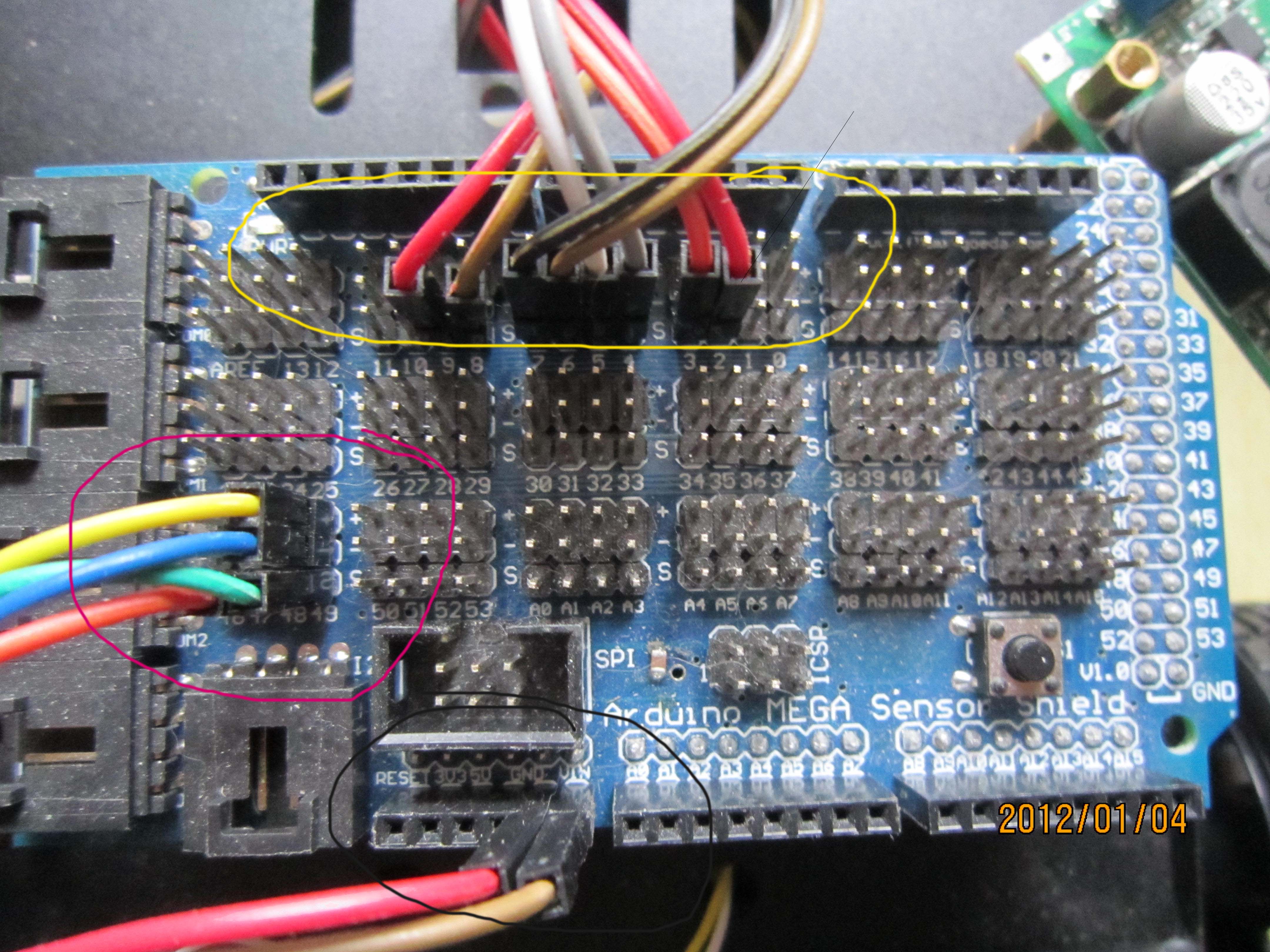 注意上图圈中的部分,其中黄线圈中的部分是电机驱动板的连线,用来控制电机驱动板。
红线部分圈中的为超声传感器的连接线。
黑色线圈中的为电源线的连接线。
其中 黑色线标记的连线与电机控制板的电源输入端,共享一个电源,也就是电机驱动板和Arduino 2560板子是并联到电池的。
接下来,我们看看 Arduino 2560 与超声传感器的链接方式

注意超声传感器有四根接线,应当如何接线呢?
具体我们是这样子的,
1.Arduino 2560 扩展版的 任意一个 “-”与超声传感器的“VCC”,注意,由于扩展版印反了,因此实际上的“-”其实是“+”
2.Arduino 2560 扩展版的 任意一个 “+”与超声传感器的“GND”,注意,由于扩展版印反了,因此实际上的“-”其实是“+”
3.超声传感器的“Trige”与 Arduino 2560 扩展版的 任意一个 数字接口连线,本例中用到了 48 号口子,原因仅仅是因为布线比较方便,其实可以任意口子。该接口应当在代码中初始化为输出端口,用来给传感器发送工作信号。
4..超声传感器的“Echo”与 Arduino 2560 扩展版的 任意一个 数字接口连线,本例中用到了 49 号口子,原因仅仅是因为布线比较方便,其实可以任意口子。该接口应当在代码中初始化为输入端口,用来读取传感器发回的数据。
至此,基本的布线已经完成。
硬件部分完成,接下来就是软件部分的逻辑了,直接先上代码
|
1 2 3 4 5 6 7 8 9 10 11 12 13 14 15 16 17 18 19 20 21 22 23 24 25 26 27 28 29 30 31 32 33 34 35 36 37 38 39 40 41 42 43 44 45 46 47 48 49 50 51 52 53 54 55 56 57 58 59 60 61 62 63 64 65 66 67 68 69 70 71 72 73 74 75 76 77 78 79 80 81 82 83 84 85 86 87 88 89 90 91 92 93 94 95 96 97 98 99 100 101 102 103 104 105 106 107 |
//this file is a example for motor control board //Control LeftFrontWheel int MosfetLeftFrontWheel0 = 8; //Left Front Wheel int MosfetLeftFrontWheel1 = 9; //Left Front Wheel int MosfetRightFrontWheel0 = 2; //right front wheel int MosfetRightFrontWheel1 = 3; //right front wheel int MosfetLeftTailWheel0 = 4; int MosfetLeftTailWheel1 = 5; int MosfetRightTailWheel0 = 6; int MosfetRightTailWheel1 = 7; //超声传感器部分 const int TrigPin = 49; const int EchoPin = 48; float cm; #define MAX_CAR_SPAN_CM 40 //CM void setup() { pinMode(MosfetLeftFrontWheel0, OUTPUT); pinMode(MosfetRightFrontWheel0, OUTPUT); pinMode(MosfetLeftTailWheel0, OUTPUT); pinMode(MosfetRightTailWheel0, OUTPUT); pinMode(MosfetLeftFrontWheel1, OUTPUT); pinMode(MosfetRightFrontWheel1, OUTPUT); pinMode(MosfetLeftTailWheel1, OUTPUT); pinMode(MosfetRightTailWheel1, OUTPUT); //超声传感器部分 Serial.begin(9600); pinMode(TrigPin, OUTPUT); pinMode(EchoPin, INPUT); } void loop() { digitalWrite(TrigPin, LOW); //低高低电平发一个短时间脉冲去TrigPin delayMicroseconds(2); digitalWrite(TrigPin, HIGH); delayMicroseconds(10); digitalWrite(TrigPin, LOW); cm = pulseIn(EchoPin, HIGH) / 58.0; //将回波时间换算成cm cm = (int(cm * 100.0)) / 100.0; //保留两位小数 Serial.print(cm); Serial.print("cm"); Serial.println(); while(cm>MAX_CAR_SPAN_CM) { //init MOSFE Pin digitalWrite(MosfetLeftFrontWheel0, HIGH); digitalWrite(MosfetRightFrontWheel0, HIGH); digitalWrite(MosfetLeftTailWheel0, HIGH); digitalWrite(MosfetRightTailWheel0, HIGH); digitalWrite(MosfetLeftFrontWheel1, LOW); digitalWrite(MosfetRightFrontWheel1, LOW); digitalWrite(MosfetLeftTailWheel1, LOW); digitalWrite(MosfetRightTailWheel1, LOW); delay(200); //停车 digitalWrite(MosfetLeftFrontWheel0, LOW); digitalWrite(MosfetRightFrontWheel0, LOW); digitalWrite(MosfetLeftTailWheel0, LOW); digitalWrite(MosfetRightTailWheel0, LOW); digitalWrite(MosfetLeftFrontWheel1, LOW); digitalWrite(MosfetRightFrontWheel1, LOW); digitalWrite(MosfetLeftTailWheel1, LOW); digitalWrite(MosfetRightTailWheel1, LOW); //delay(200); digitalWrite(TrigPin, LOW); //低高低电平发一个短时间脉冲去TrigPin delayMicroseconds(2); digitalWrite(TrigPin, HIGH); delayMicroseconds(10); digitalWrite(TrigPin, LOW); cm = pulseIn(EchoPin, HIGH) / 58.0; //将回波时间换算成cm cm = (int(cm * 100.0)) / 100.0; //保留两位小数 Serial.print(cm); Serial.print("cm"); Serial.println(); } //前方有障碍物,转弯 if(cm<=MAX_CAR_SPAN_CM) { digitalWrite(MosfetLeftFrontWheel0, LOW); //digitalWrite(MosfetRightFrontWheel0, LOW); // digitalWrite(MosfetLeftTailWheel0, LOW); digitalWrite(MosfetRightTailWheel0, LOW); digitalWrite(MosfetLeftFrontWheel1, HIGH); // digitalWrite(MosfetRightFrontWheel1, HIGH); // digitalWrite(MosfetLeftTailWheel1, HIGH); digitalWrite(MosfetRightTailWheel1, HIGH); delay(200); } } |
代码还是比较简单的,具体的控制端口,还是要根据当时布线的方便性来处理,这个都是可以变动的。
以上仅供暂时的参考,电机控制部分的代码没有使用PWM,所以,小车走走停停,呵呵,后期继续改动了,暂时就写到这里吧。