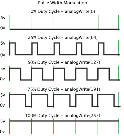
对于直流电机的速度控制,目前流行的控制逻辑是PWM,关于 Arduino 的PWM,看看图片

板子上标注了“PWM”的区域就是管脚均可以用于这种输出。使用的函数是:
|
1 |
analogWrite(pin, value); |
注意value值的范围是0~255。
PWM 英文是“Pulse-width modulation” ,PWM是用占空比不同的方波,来模拟“模拟输出”的一种方式。简而言之就是电脑只会输出0和1,那么想输出0.5怎么办呢?于是输出01010101….,平均之后的效果就是0.5了。
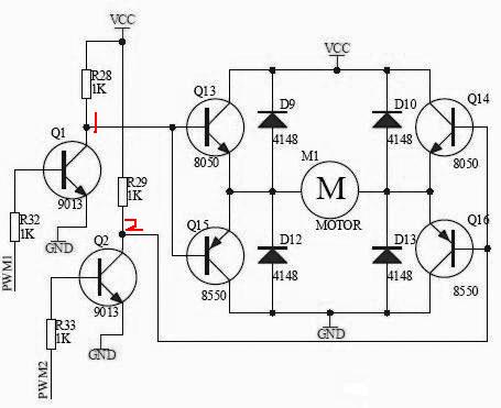
现在看看电机的常规驱动电路,H桥

使用单片机来控制直流电机的变速,一般采用调节电枢电压的方式,通过单片机控制PWM1,PWM2,产生可变的脉冲,这样电机上的电压也为宽度可变的脉冲电压。根据公式
U=aVCC
其中:U为电枢电压;a为脉冲的占空比(0<a<1);VCC直流电压源,这里为5V。
电动机的电枢电压受单片机输出脉冲控制,实现了利用脉冲宽度调制技术(PWM)进行直流电机的变速。

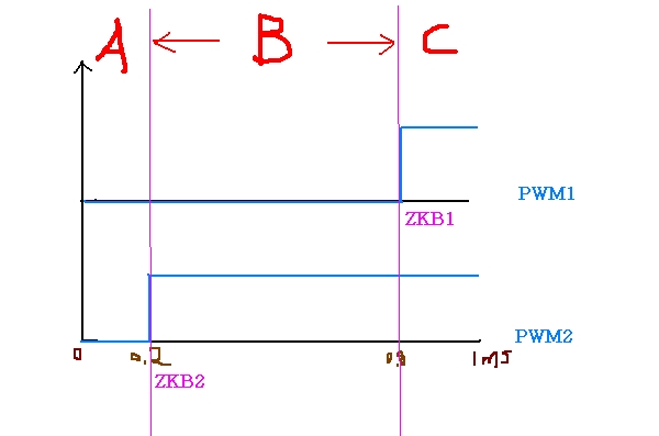
因为在H桥电路中,只有PWM1与PWM2电平互为相反时电机才能驱动,也就是PWM1与PWM2同为高电平或同为低电平时,都不能工作,所以上图中的实际脉冲宽度为B,
我 们把PWM波的周期定为1ms,占空比分100级可调(每级级差为10%),这样定时器T0每0.01ms产生一次定时中断,每100次后进入下一个 PWM波的周期。上图中,占空比是60%,即输出脉冲的为0.6ms,断开脉冲为0.4ms,这样电枢电压为5*60%=3V。
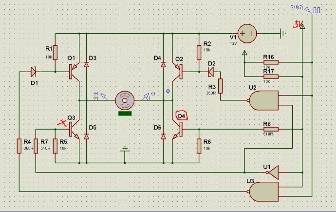
我们讨论的是可以正转反转的,如果只按一个方向转,我们就只要把PWM1置为高电平或低电平,只改变另一个PWM2电平的脉冲变化即可,,如下图(Q4导通,Q3闭合,电机只能顺时针调整转动速度)

下面看看摘抄的部分原理
直流电动机转速n=(U-IR)/Kφ
其中U为电枢端电压,I为电枢电流,R为电枢电路总电阻,φ为每极磁通量,K为电动机结构参数。
直 流电机转速控制可分为励磁控制法与电枢电压控制法。励磁控制法是控制磁通,其控制功率小,低速时受到磁饱和限制,高速时受到换向火花和换向器结构强度的限 制,而且由于励磁线圈电感较大动态响应较差,所以这种控制方法用得很少。大多数应用场合都使用电枢电压控制法。随着电力电子技术的进步,改变电枢电压可通 过多种途径实现,其中PWM(脉宽调制)便是常用的改变电枢电压的一种调速方法。
PWM调速控制的基本原理是按一个固定频率来接通和断开电源,并根据需要改变一个周期内接通和断开的时间比(占空比)来改变直流电机电枢上电压的"占空比",从而改变平均电压,控制电机的转速。在脉宽调速系统中,当电机通电时其速度增加,电机断电时其速度减低。只要按照一定的规律改变通、断电的时间,即可控制电机转速。而且采用PWM技术构成的无级调速系统.启停时对直流系统无冲击,并且具有启动功耗小、运行稳定的特点。
设电机始终接通电源时,电机转速最大为Vmax,且设占空比为D=t/T,则电机的平均速度Vd为:
Vd=VmaxD
由公式可知,当改变占空比D=t/T时,就可以得到不同的电机平均速度Vd,从而达到调速的目的。严格地讲,平均速度与占空比D并不是严格的线性关系,在一般的应用中,可将其近似地看成线性关系。 在直流电机驱动控制电路中,PWM信号由外部控制电路提供,并经高速光电隔离电路、电机驱动逻辑与放大电路后,驱动H桥下臂MOSFET的开关来改变直流电机电枢上平均电压,从而控制电机的转速,实现直流电机PWM调速。
原理知道了,那么看看 Arduino Mega 2560 的PWM控制端口信息
1) Arduino 2560 has 12 pins supporting PWM. They are from 2 to 13 included.
2) the PWM default frequency is 490 Hz for all pins, with the exception of pin 13 and 4,whose frequency is 980 Hz (I checked with an oscilloscope).
3) In order to change frequency on pin 'A', we have to change some value in the timer (or register), controlling pin 'A'. This is the list of timers in Arduino Mega 2560:
timer 0 (controls pin 13, 4);
timer 1 (controls pin 12, 11);
timer 2 (controls pin 10, 9);
timer 3 (controls pin 5, 3, 2);
timer 4 (controls pin 8, 7, 6);
As you can see, a given timer controls more than one pin (every change about a timer will affect all pins depending on it!).
4) You can access a timer simply changing in your code (tipically in the setup()), the value of variable TCCRnB, where 'n' is the number of register. So, if we want to change the PWM frequency of pins 10 and 9, we will have to act on TCCR2B .
5) The TCCRnB is a 8 bit number. The first three bits (from right to left!) are called CS02, CS01, CS00, and they are the bits we have to change.
Those bits in fact represent an integer number (from 0 to 7) called 'prescaler' , that Arduino uses to generate the frequency for PWM.
6) First of all, we have to clear these three bits, i.e they must be all set to 0:
|
1 2 |
int myEraser = 7; // this is 111 in binary and is used as an eraser TCCR2B &= ~myEraser; // this operation (AND plus NOT), set the three bits in TCCR2B to 0 |
7) now that CS02, CS01, CS00 are clear, we write on them a new value:
|
1 2 |
int myPrescaler = 3; // this could be a number in [1 , 6]. In this case, 3 corresponds in binary to 011. TCCR2B |= myPrescaler; //this operation (OR), replaces the last three bits in TCCR2B with our new value 011 |
now we have a new PWM frequency on pin 9 and 10!
I registered those values on all PWM pins, changing the value of prescaler (the only exception are pins 13 and 14, see later):
prescaler = 1 ---> PWM frequency is 31000 Hz
prescaler = 2 ---> PWM frequency is 4000 Hz
prescaler = 3 ---> PWM frequency is 490 Hz (default value)
prescaler = 4 ---> PWM frequency is 120 Hz
prescaler = 5 ---> PWM frequency is 30 Hz
prescaler = 6 ---> PWM frequency is <20 Hz
(prescalers equal t 0 or 7 are useless).
Those prescaler values are good for all timers (TCCR1B, TCCR2B, TCCR3B, TCCR4B) except for timer 0 (TCCR0B). In this case the values are:
prescaler = 1 ---> PWM frequency is 62000 Hz
prescaler = 2 ---> PWM frequency is 7800 Hz
prescaler = 3 ---> PWM frequency is 980 Hz (default value)
prescaler = 4 ---> PWM frequency is 250 Hz
prescaler = 5 ---> PWM frequency is 60 Hz
prescaler = 6 ---> PWM frequency is <20 Hz
Note that timer 0 is the one on which rely all time functions in Arduino: i.e., if you change this timer, function like delay() or millis() will continue to work but at a different timescale (quicker or slower!!!)
明天修改一下电机的控制代码,把小车代码修改一下,哈哈